In data modeling, explaining how each table links to another is known as cardinality. Knowing how to establish table cardinality is a key skill in database design because it can identify areas where the normalization process may have gone awry. This article looks at each relationship type more closely.
In data modeling, explaining how each table links to another is known as cardinality. Tables can be related as any of: one-to-one, one-to-many, or many-to-many. Knowing how to establish table cardinality is a key skill in database design because it can identify areas where the normalization process may have gone awry. Today, we’ll be looking at each relationship type more closely and learning how to represent them in a diagram.
Defining a Primary Key
Selection of the primary key is of paramount concern because it will link a table to another in every type of relationship. The following diagram from my Disambiguating between Duplicate Column Names in MySQL article exemplifies a one-to-many relationship between the shops and employees tables. Hence, each unique shop_id in the shops table relates to multiple records of the employees table:
It also demonstrates the use of an ID field to link the tables. The shop_id is used instead of the shop name for several good reasons. First, it would use up a lot more storage space in the database to store the shop names in every table that referred to them. Second, it is much quicker to query on indexed fields than text values. Third, text values have a habit of changing over time. Case in point, we maintain a list of airports in our databases. You’d be surprised just how often airports change names! For instance, Montreal’s Dorval airport was renamed some time ago to the Pierre Elliot Trudeau airport. It was a lot easier to change the text value in the airports table than perform a search and replace in every table that referred to that airport! Finally, the simple shops table used here only contains one text description field. In our code tables, we have four: both a French and English as well as a short and long description! I’d hate to try to decide which description to use for table joins. Would we include all of them, just to be safe? Better to use an index.
For all the reasons listed above:
ALWAYS REPRESENT EACH UNIQUE VALUE WITH A NUMERIC ID
Let’s now look at each relationship type in more detail and examine what features are unique to each.
The One-to-One Relationship
A one-to-one relationship occurs when one entity is related to exactly one occurrence in another entity. In database terms, one-to-one relationships occur when there is exactly one record in the first table that corresponds to exactly one record in the related table. Here’s an example:
A database contains a table named “stock” and another named “company_details”. For every company, there is expected to be one accompanying stock entry:
|
stock
|
|
company_details
|
|
ticker_id
|
|
listing_name
|
|
exchange_id
|
|
date_listed
|
|
1 to 1
|
|
ticker_id
|
|
name
|
|
description
|
|
date_incorporated
|
|
While MySQL does not have any “ready” options to define the one-to-one relationship, if you want to enforce it, you can add a foreign key from one primary key to the other primary key. The primary key has to be unique, so by doing this, the two tables will have the one-to-one relationship by default.
The One-to-Many Relationship
A one-to-many relationship occurs when one entity is related to many occurrences in another entity. In database terms, one-to-many relationships occur when there is exactly one record in the first table that corresponds to many records in the related table. In a one-to-many relationship, the foreign key, although indexed, is not unique. Here is another table called “stock_daily_performance”. For every record in the stock table, there can be several related rows in the stock_daily_performance table:
|
stock
|
|
stock_daily_performance
|
|
ticker_id
|
|
listing_name
|
|
exchange_id
|
|
date_listed
|
|
1
to
many
|
|
daily_performance_id
|
|
opening_price
|
|
closing_price
|
|
volume
|
|
date
|
|
ticker_id (FK)
|
|
To define the one-to-many relationship, you can add a foreign key to a table that links to the primary key in another table.
The Many-to-Many Relationship
Many-to-many relationships occur when each record in an entity may have many linked records in another entity and vice-versa. In a many-to-many database table relationship, one record in either table can relate to many records in the other table. It is the hardest relationship to understand and define correctly. One complicating factor is that it requires being broken down into two one-to-many relationships and creating a new junction table to stand between the two existing tables.
Here are two tables whose relationship has not yet been defined:
|
stock
|
|
category
|
|
ticker_id
|
|
listing_name
|
|
exchange_id
|
|
date_listed
|
|
(many to many)
|
|
category_id
|
|
name
|
|
description
|
|
Many-to-many relationships can be defined by having a hasMany on each side of the relationship with at least one side having a belongsTo property. Hence, a stock hasMany categories, such as “small cap”, and “financial”. Similarly, a stock category hasMany stocks. IBM, Microsoft, and Sun Systems are all examples of Technology funds. The problem is that we cannot directly link the tables using the primary key, as they cannot be duplicated, which would be a requirement of the many-to-many relationship. Therefore, to link the tables, we must create a third, “junction” table. Besides having its own primary key, it will store both the stock and category IDs as foreign keys. These foreign keys indicate how the tables are related:
|
stock
|
stock_category
|
category
|
|
ticker_id
|
|
listing_name
|
|
exchange_id
|
|
date_listed
|
|
|
stock_category_id
|
|
stock_id (FK)
|
|
category_id (FK)
|
|
|
category_id
|
|
name
|
|
description
|
|
Relationship Diagrams
For most people, a picture is worth a thousand words. In the realm of data modeling, it definitely helps to be able to quickly get a visual of the various table relationships. Here are a couple of popular ways to visually denote table cardinality.
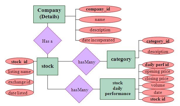
Entity-relationship Diagram
An entity-relationship (ER) diagram is a specialized graphic that illustrates the interrelationships between entities in a database. ER diagrams often use symbols to represent three different types of information. Boxes are commonly used to represent entities. Diamonds are normally used to represent relationships and ovals are used to represent attributes. Here is an ERD depicting the relationships declared above:
UML Data Modeling
The Unified Modeling Language (UML) diagram describes the structure of a system by showing the system’s classes, their attributes, and the relationships between the classes. It is the standard language for modeling business and software application requirements. Its flexibility allows for many different types of modeling, such as understanding the business process, workflow of events, sequence of queries, applications, databases, architectures, and more. Since it can be used for both Object-oriented class design and to identify database table relationships, it makes data attributes much easier to map between the class objects and the underlying database tables that store them.
Whereas ER models present a conceptual model of the entity relationships, UML diagrams present them in a more physical form. In fact, there are a number of software products that can create a database from the UML diagram.
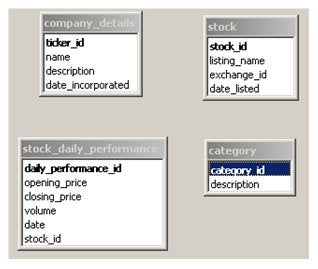
To create a UML diagram:
1. Begin by listing every table as a box with their attributes (fields) listed inside:
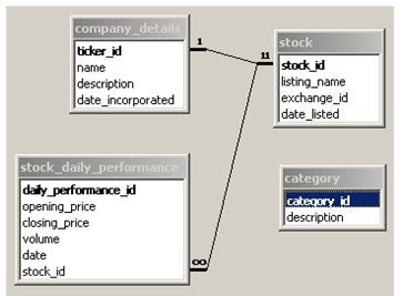
2. Next, link primary and foreign keys together by drawing a connecting line.
3. Include the cardinality above the line, next to the attribute:
4. Add junction tables for many-to-many relationships. Recall that the stock and category tables have a many-to-many relationship. As such, we can’t link them directly. Instead, we have to create a junction table called stock_category, which will then have two one-to-many relationships, using each table primary key as foreign keys:

More about Cardinality
There are several ways to denote cardinality in UML diagrams. None are more correct than another. It’s simply a matter of what you’re accustomed to.
In the example above, we used Chen notation. It uses a numeric one (1) indicates the one in a one-to-one or one-to-many relationship. The many can be indicated using an “n” or infinity symbol (∞).
In UML associations, multiplicity is used on those associations to denote cardinality, using the following conventions:
|
Left
|
Right
|
|
Example
|
|
1
|
1
|
one-to-one
|
person <-> weight
|
|
0..1
|
1
|
optional on one side one-to-one
|
date of death <-> person
|
|
0..* or *
|
0..* or *
|
optional on both sides many-to-many
|
person <-> book
|
|
1
|
1..*
|
one-to-many
|
person <-> language
|
Chen notation is more prevalent in the United States, while Crow’s Foot notation is used primarily in the UK. It uses the ends of the relationship lines to represent the cardinality of the relationship:
Conclusion
Knowing how to establish table cardinality is a key skill in database design because it can identify areas where normalization may not be optimal or was incorrectly applied. Usually, when related tables cannot be mapped using one of the three relationship types covered today, it means that you have to take a step back and reconsider the break down of the entities. Often times, a table will still contain overlapping data, which needs to be broken down further.
» See All Articles by Columnist Rob Gravelle


